Posts

Showing posts from April, 2022

the only thing I hate is entropy

 And yes, I am undoubtedly misapplying a sub-atomic scale idea to human scale realities so I won't try to define the term, entropy.  But it really irks me that things break or wear out or are hard to fix.  Evidence is littered all around me, the unmovable automobiles, unrideable bicycles, broken appliances, battery operated stuff with so much battery leakage that it's hard to get the door off the battery compartment. And there's not much I can do about preventing it.  That's the way the universe seems to work. But one positive thing I can do to combat this concerns kits.  I really try to provide continuing support for the kits, I still have repair parts for most of them.  I've always put my call on the circuit boards so anyone with access to a search engine should be able to contact me by email even if they don't know what the item is. I generally like to try and fix things via an email conversation.  Often a high-resolution picture of the non-working kit may he

pancake recipe to go with maple syrup

Image
Forgot to mention one thing in the previous maple syrup blog entry https://wb9kzy.blogspot.com/2022/04/2022-maple-syrup-wrap-up.html and that was what I use the maple syrup for:  to sweeten and moisten my pancakes.   So here is my latest recipe for small batch of pancake batter:   1/2 cup whole wheat flour 1/4 teaspoon baking soda 1/4 teaspoon baking powder 1 egg 1 tablespoon olive oil 4 ounces of milk Blend the dry ingredients together in one bowl and beat the wet ingredients in another bowl and then combine them and let them set a little while the oiled pan heats up. Add more flour or milk as needed to adjust the batter consistency to your liking.  The batter can be mixed vigorously, the whole wheat flour won't get all gluteny and tough.   they look better in real life, taste good, too !   Here they are cooked at a little higher than medium heat on an electric range, small burner in a small, black Teflon fry pan (from Manitowoc !). that's the problem with selling stuff that l

Paypal ?

Image
 source: https://3dprint.com/159318/prusa-paypal-service-problems/ Paypal lured me in with a "free" $5 deposit in my account.  As I recall there was also a competitor called Payplace that gave $10 to new accounts.  But Paypal took over fairly quickly, maybe due to Ebay ? Anyway this entry kind of goes along with a previous blog entry on DX sales.  In 2021 I finally stopped accepting Paypal for almost all orders.  It was a combination of things that prompted the change (in no particular order): 1) DX sales:  I had already stopped DX sales which really do require something like Paypal.  People don't mail "green stamps" like they used to.  So no DX sales means less reason for Paypal. 2) rates/fee increases:  Paypal raised both the per transaction fee AND the percentage of sales taken in 2021.   And over the years Paypal has changed things so that the seller pays a fee anytime someone completes a transaction, even if a partial refund is done - when it started Paypal

Death and kit sales

 I remember a customer of mine who bought quite a few chips from me emailing what I thought at the time was a strange question:  "Did my heirs have a plan of action with regard to my business IF I should die ?  How would he be able to keep obtaining product from me ?"  Well I thought about it and contacted someone and arranged to have the commerce continue even if I died. The ironic thing is that of all the people involved, my customer, his sales rep, my friend who would have taken over the sales, my Dad who would have been my Personal Representative (executor of the will) I am the only one who is still living.   But it was a sensible thing to ask, loss of a single source of a critical component could be a big hassle for sales of a product.  Getting your suppliers thinking about the need to prepare for death ahead of time is the undeniably logical, Spockian, approach to life. I remember another customer who purchased chips in quantity from me.  He would periodically email me

2022 Maple syrup wrap-up

Image
 I went out today and got less than 2 liters of somewhat cloudy maple sap, this was from 2 days since I didn't go out the day before.  Also, the sap doesn't taste as sweet as usual.  I think it's probably time to pull the taps and end the 2022 season. According to my somewhat slipshod record keeping I've processed 244 liters of maple sap or 61 boils of 4 liters each.  11 trees were tapped so that's an average of 22 liters per tree (over 5.5 gallons).   That boiled down to roughly 10.6 liters of what I call "pre-syrup" - it's brown, sweet, a little cloudy and runny. But true maple syrup is 2/3 sugar, 1/3 water, so additional boiling is required to get to true syrup.  Assuming an average 40:1 boil concentration ratio that means that I'd have to boil that 10.6 liters of pre-syrup down to 6.1 liters of real syrup. I think I'm going to skip that, just use it the way it is.  It won't be that much more runny than real syrup and it won't be qui

A quarter century !

Image
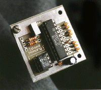
 Recently an email was received concerning the Island Memory kit. http://wb9kzy.com/imem.htm   This is a discontinued kit that provided programmable memories for keyers (like the Accu-keyer) that didn't have memory.  The correspondent was looking for documentation for the kit.  He had acquired a circuit board and nothing else: built but unused for over 20 years ? The label on the microcontroller chip has a purpose.  I had purchased a quantity of the Motorola 68HC705j1a chips at a low price.  The only problem was that all the marking on the chips had been ground off.  I don't know why they did this - this used to be done by some ham radio accessory vendors, they'd grind off the part number or paint over them (blacktop) to hide the circuit from hams who might want to duplicate it :)  But in this case the label is there to obscure not the part number but the fact that the top was ground down. BTW, grinding or sanding the top of an IC is a BAD idea as far as possible static dam

DX sales

Image
 Don Lancaster says this about DX sales on ebay: source: https://tinaja.com/glib/myebays.pdf But I ignored his advice with my kit sales for many years.  For one thing the need to fill out the customs form and use lots of stamps went away with online label generation.  The USPS also added tracking of international parcels (although at a hefty price).  Also, from the start I took the advice of a fellow internet seller and always priced the kits and the shipping with even dollar amounts.  Many DX customers in the early days would mail US Currency so even dollar pricing made this easier.   But in 2021 I stopped selling to DX customers.  The pandemic made mail delivery and tracking overseas unreliable.  I was frustrated having to resend items.  Customers were frustrated due to slow delivery times.  The breaking point was a parcel sent to Australia.  A ban on certain mail to Australia went into effect right after I sent the kits - I did get the parcel and my money back but it was irritating

Rumors of their demise . . .

Image
source 4-22-2022: https://www.kenwood.com/usa/com/amateur/ I was listening to a net yesterday. A ham was telling how Kenwood did him wrong on a rig repair job. And then he repeated a rumor that Kenwood was out of the Amateur Radio business.  Another ham on the net told the first ham that he actually worked for Kenwood and that Kenwood was still very much in the ham business. The first ham then responded that he had heard something from someone in Japan and basically stood by his assertion that Kenwood was no longer a supplier to hams. Well the second ham didn't press the point, he seemed a little worried about the conversation turning commercial and just let it drop.  How should hams respond to this kind of rumor ?  I think that most hams are unlikely to want to get into a big argument, especially on the air, so it doesn't get challenged. But this wasn't politics or religion - it was a simple matter of fact.  On this particular net they recently lost a net control bec

those pictures !

Image
 You know how it is, a funny picture comes to your attention and you need to share it with others.  In the olden days of the 20th century it might get stapled to a mailing list and routed around the office. I sent this picture (uncredited from Facebook, of course) to some people I used to work with, all test engineers: source: https://www.kg4cyx.net/img_20190918_144116_dro/ So I then get this picture in return: source: https://f4.bcbits.com/img/a0324090507_10.jpg Which reminded me of when I was a kid taking a couple of D cells apart (modern kids must be disappointed with alkaline cells, no carbon rod).  Unfortunately I took off the metal terminals while cleaning the carbon electrodes.   So I sawed a groove in each of the rods and then tried to solder some copper wire to them (which didn't work). I then plugged the wires into the wall socket.  I touched the two carbon rods together (holding the wires by the insulation, for safety !).  I was hoping for a carbon arc but what happened

keeping it stock, full mods or in between ?

Image
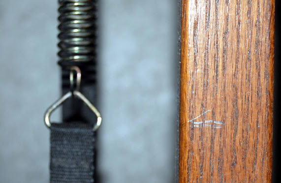
 I thought of my Grandfather, Charles Olson, today.  I had noticed that the tension strap on my exercise machine is starting to fray.  So I wanted to note the spring tension that it puts on the flywheel.  For various reasons the tension scale on the machine is worthless.  So I took a pencil and made a mark on the nicely finished piece of oak that was used by Nordic Track on their ski machines. It's been marked - no longer stock My Grandparents lived in Milwaukee in "The Stone House" on 40th street near Lincoln Creek: spent quite a few Sunday afternoons at this house It was a 2 bedroom house, nicely furnished.  At the entrance there was a coat closet and I suspect that today if the door to that closet was opened and the door jamb near the hinge was examined there would be pencil marks and dates by my Grandfather.  A "permanent" record of my increases in height.  But hidden away, not a public conversation starter. So does that qualify as keeping that house "s

channel 20 in Chicago

Image
 When I lived in the Chicago area in the 1970s/80s/90s one of the TV stations I watched was channel 20, WYCC  (the call letters stood for Your City Colleges, something like that ?).  It was an adult education channel.  I  remember a few of the shows such as French in Action  and  Against all Odds: Inside Statistics. One was a movie series in which Eisenstein's silent movie:  Battleship Potemkin, was repeated numerous times.   If you've never seen it I'll spoil it slightly by mentioning the scene of the maggot ridden meat don't tell me they're protein but also the famous Odessa steps scene with the baby carriage. down the steps on metal wheels !   The movie: "The Untouchables" had a similar scene in a Chicago railway station lobby. at least they've got rubber tires in Chicago   BTW, another famous stairs + gunfire scene is in the movie: The Hidden Fortress the scenes on the stairs were amazing And of course The Hidden Fortress was the inspiration for

When the internet changes it's usually for the worse

Image
 I remember in the dim past, the late 20th century, I first gained access to the internet by email.  This was done via the SBAonline BBS.  It was really wonderful, the SBA had a dial up BBS with an 800 number.  It had message areas, and of course it allowed the user to sign up and receive an email address.  With that it was possible to do searches and join email lists (like qrp-l).  As you might imagine it didn't last that long.   So I signed up for AT&T Worldnet.  It also had dialup access via an 800 number but with monthly and per minute access charges.  So I was able to continue with the email lists and also start selling kits and eventually had a web site: But you can see that the Wayback stopped crawling my site in 2008-9. jacksonharbor.home.att.net life span home.att.net/~jacksonharbor alternate URL lasted a little longer ?   This was due to ATT dropping Worldnet.  Maybe they didn't want to make a few dollars a month from people when they could lose bushels of dollars

Rodrigues

Image
 For many when it comes to cartoons and ham radio there is only Gil (Phil Gildersleeve).  Also Robert Beasley did a number of cartoons for QST.  Even some Dilbert cartoons were sorta related to radio.  But when I was a kid I subscribed to Electronics Illustrated.  One of the attractions was the page of cartoons, "Over and Out", in each issue drawn by Charles Rodrigues.  He also was published in Popular Electronics. My favorite kit cartoon: Electronics Illustrated July 1969 Another kit cartoon: Popular Electronics April 1965 The first radio clock ? Electronics Illustrated March 1964 Per this site http://comicstripfan.com/newspaper/c/caseythecop.htm Mr. Rodrigues is no longer with us.  Luckily worldrdiohistory.com has an almost inexhaustible supply of the old electronics magazines with his artwork. Best Regards, Chuck, WB9KZY http://wb9kzy.com/ham.htm

MOSFET rectifier design for the economy bipolar supply

Image
 Doing a lot of cribbing from the original MOSFET bridge rectifier design, here is my try at a half-wave MOSFET rectifier for the economy bipolar supply.  Two MOSFETs and two opamp sections are used.  MOSFET half-wave bipolar supply rectifier The main change is only two resistors are used for input waveform sampling - this was done since there would be no way to terminate two more resistors anywhere else other than ground.  A second pair of resistors could be used if there was a reason to isolate the two opamp  minus inputs. Here is the simulated loaded output of the half-wave rectifier:  100 ohm loads on both outputs As with the original bridge circuit, the gate drive varies depending on the load. Here is the output from a lightly loaded supply (just the sampling resistors).  no loads other than voltage dividers The gate drives are just a little bit of "scratchiness" near the positive and negative input voltage peaks. Since it's simpler than the bridge circuit this half-

Full-wave MOSFET rectifier design

Image
 This design basically is a cut-down version of the MOSFET bridge rectifier presented recently.  Two p-channel MOSFETs and two opamp sections are used.  The n-channel MOSFETs and their two driving opamp sections were deleted.  Also the 12.6 VAC center tapped transformer was simulated with two 6.3 VAC (8.9 = 6.3 x 1.414) sources in series with their common connection grounded. full wave MOSFET rectifier As with the original bridge circuit and the half-wave circuit, the gate drive varies depending on the load. Here is the output from a lightly loaded supply (just the sampling resistors).  lightly loaded full wave input-output-gate drive The gate drives are off with just a little bit of "scratchiness" near the positive and negative input voltage peaks.    Here is the output simulation with a 100 ohm load:  full wave rectifier with 100 ohm load The gates are on for a longer period but cut off just after the peak input voltage. The design might be made better by using the two n-ch

Understanding the MOSFET rectifier circuit

Image
 After doing a little more simulating with LTspice I can see why my simple effort at a MOSFET rectfier for the economy bipolar supply didn't work.  The reason is that as long as the MOSFET is ON, the channel conducts, in either direction !  So it's not like a diode where the conduction ends roughly when the cathode and anode are at equal voltage.  Thus with the MOSFET the output voltage follows the waveform back down because the MOSFET discharges the capacitor into the AC input voltage source (transformer).  This also explains why the MOSFET gets warm, the rather large cap is being charged and discharged each cycle through the MOSFET. The opamp (as a quad comparator) and the pair of voltage dividers are used to turn on the MOSFET only when the input voltage is higher than the capacitor voltage. I added some probe points on the 4 gates of the MOSFETs in this schematic and also added a more substantial 100 ohm load: MOSFET rectifier with gate probes and 100 ohm load And looking a

Simulating the MOSFET rectifier

Image
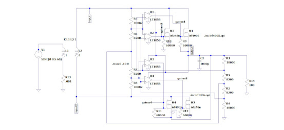
 Before firing up the MOSFET rectifier circuit from yesterday on a breadboard I thought I'd try simulating it with LTspice, here is the schematic: MOSFET rectifier entered into LTspice I'm still taking baby steps on LTspice - for some reason I thought it would be time to update  to the latest version.  This really didn't make any difference. I also had trouble with the simulation and I thought it might be due to the way I was applying the AC to the rectifier.  So a transformer was added using L1 and L2.  I kept the ratio at 1:1 and just fed L1 with 1.414 x 6 V to get the peak input voltage of 8.5 volts. And I didn't see the TL084 opamp as an option so I selected what appears to be the Linear Technology equivalent (DIP, quad, JFET inputs) LT1058. At first the circuit did seem to simulate full wave rectification but when I tried adding a capacitor on the output the voltage didn't come up to near the peak as it should with only a string of high value resistors as a loa

a complex MOSFET rectifier circuit

Image
 While trying a MOSFET rectifier for the economy bipolar supply  https://wb9kzy.blogspot.com/2022/04/idea-on-economy-bipolar-supply.html I found this circuit diagram for a MOSFET based rectifier: MOSFET rectifier circuit by Wolfgang Schubert It seems really complex and I haven't had a chance to try it but it is originally from Elektor magazine, the July-August 2006 edition, page 42:, here it is on the World Radio History site https://worldradiohistory.com/UK/Elektor/00s/Elektor-2006-07-08.pdf Does this make sense for higher voltages, like a 13.8 volt ham rig supply ?  As amateurs do we really even care ?  :)  Why not try something new ?   I still intend to build my own power supply and was thinking that possibly I could use two 6.3 volt transformers with the taps selected for slightly higher output instead of the usual 18 volt transformer usually spec'd for a 13.8V supply.  And do I really even need 13.8 V, maybe 12.6 V would be enough ? Anyway, with less voltage loss in the r

May 2022 issue of QST

Here is the text of an email received from the ARRL on April 6, 2022:     http://www.arrl.org/member-bulletin?issue=2022-04-05 The May 2022 issue of QST was received here on the island on April 11, 2022.  And the paper is noticeable at once as different from normal.  It's kind of like a hometown newsletter that has been printed on a color laser copier or inkjet printer.  The cover paper still has the smooth, glossy, "slick" finish but the inside pages are rough to the touch and have a bleedy appearance. It's not horrible but hopefully just a temporary thing until more suitable paper is found.  As I recall magazines used to be divided into the "slicks" (like Life magazine) and the "pulps" (like science fiction magazines) - the May 2022 QST is kind of between those two extremes. On a happier note the ARRL cutover to their latest web site seems to have gone well.  At least my favorite link to the Periodicals Archive and Search http://www.arrl.org/arrl

Are you a wiper or a flicker ?

Image
 I remember one time in the ham radio club shack during high school I was listening to the Swan 400 while a couple of the club members were working at the bench across the room.  One of the guys (no names will be mentioned to protect basically nobody ;) was soldering and as some of us do, flicked some excess solder off the iron tip.  Unfortunately the solder found it's way to a leg of the other fella, caught him right where the leg meets the foot.  Well, there was some yelling and epithets expressed and eventually a shoe/sock removed and it was determined that nothing super serious happened. The moral for me was:  don't kibbitz while someone is soldering ! So are you a wiper or a flicker ?  I guess I'm both but when I do wipe I usually do it on one of these: maybe steel would be a cheaper substitute ? The idea is that the metal scrubber will clean the tip fairly well but it won't cool the tip as much as a wet sponge.  And there's no need to periodically wet the spon

idea on economy bipolar supply

Image
After taking off the lid from another project I noticed a p-channel MOSFET in series with the positive lead from the power connector to the circuit.  It's a reverse polarity protection circuit.  Although a more elaborate circuit is supposed to be used, this just connects the gate of the MOSFET to ground, the drain to the input and the source to the circuit to be protected.  If the power polarity is correct the gate is lower in voltage than the source and the transistor turns on.  But if the polarity is reversed the gate is higher in voltage than the source and the transistor is off.   In effect this gives the protection of a series diode but with possibly a smaller forward voltage drop, depending on the spec of the MOSFET. Why not try this in the economy bipolar power supply ?  (see previous blog post:  https://wb9kzy.blogspot.com/2022/04/economy-bipolar-supply.html ) A p-channel MOSFET used for the positive rectifier and an N-channel MOSFET for the negative rectifier ? MOSFETs in