Posts

Showing posts from July, 2023

new background picture and Digi-key ad on Youtube ? (crummy commercials)

Image
 For some reason felt the need to change the background picture to this: source:  https://www.youtube.com/watch?v=6_XSShVAnkY will change it back to the QSL at a future date.  For one thing, blogger is just awkward as far as stuff like background pictures.  As with many things on the internet, I suspect that the people developing the content never actually use or consume the same content. BTW, I remember hearing Charles Kuralt on the CBS Sunday Morning program say something to the effect of:   Neutrality means that while you don't have any enemies, you don't have any friends either. And the Wander Corporation, the makers of Ovaltine during the 1930s/1940s was a Swiss corporation - 'nuff said !   Second crummy commercial: while on Youtube (in a private window so no history) a Digi-key ad was served: This just seemed weird, am I outed as a Digi-key customer even while browsing privately ?  Apparently the AI and/or the algorithm knows everything ? There is no way to change a c

Internet Holiday

Image
I'm not sure exactly what happened but sometime after 10am Friday morning I lost the DSL connection to Frontier.  It stayed off until sometime between 9pm Saturday evening and 3:20am Sunday morning. Usually I turn off my DSL modem when not using it, especially at night.  But maybe it's supposed to be left on so that firmware updates can be done ?   I did leave it on Saturday night/Sunday morning. Anyway, I was able to read a book and also work on a new kit idea so that was good. Best Regards, Chuck, WB9KZY http://wb9kzy.com/ham.htm

Who cares if the trains are on time ?

Image
 What you really want is for trains to be plentiful and uncrowded.  But everyone has heard this about baldo Benito: https://www.bloomberg.com/news/articles/2016-11-15/stop-saying-mussolini-made-the-trains-run-on-time For some reason this reminded me of one time when I was on an elevated train platform in the Chicago Loop, 20th century, maybe going home from jury duty at the Daley center ?  I was sitting there waiting for a train when one pulled in.  It wasn't the train I wanted, I was probably waiting for the Lake-Dan Ryan.  Anyway, an older lady comes up the stairs and bellows out: "HOLD THE TRAIN !" And the nebbish conductor (with his head out the window) says something like: "Lady, I've got a schedule, I can't hold the train" In the meantime the old lady has walked up to the conductor's train car and blocked the open door with her body.  After a little while another little old lady comes up the stairs, walking slower than the first.  And the condu

pot position digitizing

Image
 I've been using this idea for a long time: from page 199 of a book called: The Best of Byte: https://archive.org/details/best_of_byte_volume_1_1977_06 At first I used it with the Z-80 based Exidy Sorcerer using the 555 circuit.  But then I remembered the idea while coding the original Island Keyer kit: http://wb9kzy.com/ikeyr.htm However instead of using a 555 timer I just used an I/O pin of the microcontroller (at first the Motorola 68HC705J1A and then the various PIC keyer chips).   The idea was to: 1) charge up a timing cap (in parallel with the pot) to +5 volts with the I/O pin set to output 2) then change the I/O pin to an input and wait (while keeping track of the elapsed time) until the capacitor had discharged through the pot below the switching level of the pin 3) then the elapsed time would provide a good idea of the position of the pot which could then be used to set the keyer code speed It works well providing a linear readout of the pot position and uses no current wi

Another failed kit experiment

Image
 An idea occurred to me: combine the Keyer Enclosure kit (with a MegaPK-II keyer installed) http://wb9kzy.com/keyerenc.htm  with the PICPADL kit: http://wb9kzy.com/picpadl.htm And this resulted: Actually I usually use the same combination but with the PICPADL in a separate Altoids tin cabled to the Keyer Enclosure kit.  But I thought mounting the paddle directly to the enclosure might be handier. It wasn't, in fact the paddle seemed to act weirdly, sometimes sticking ON and other times ignoring presses.  And this was just practicing without actually keying a transmitter.  I guess I should have listened to my own advice using a metal enclosure for the paddle.  Also it looks bad.  An idea worth trying but no cheroot  :) I suppose the PICPADL could be mounted within the case screwed to the underside of the top plate.  But the problem would be cutting a slot into the Bakelite/phenolic case cleanly and accurately.  Also the battery would be in the way - I'll keep thinking about it.

Murata trimmer caps

Image
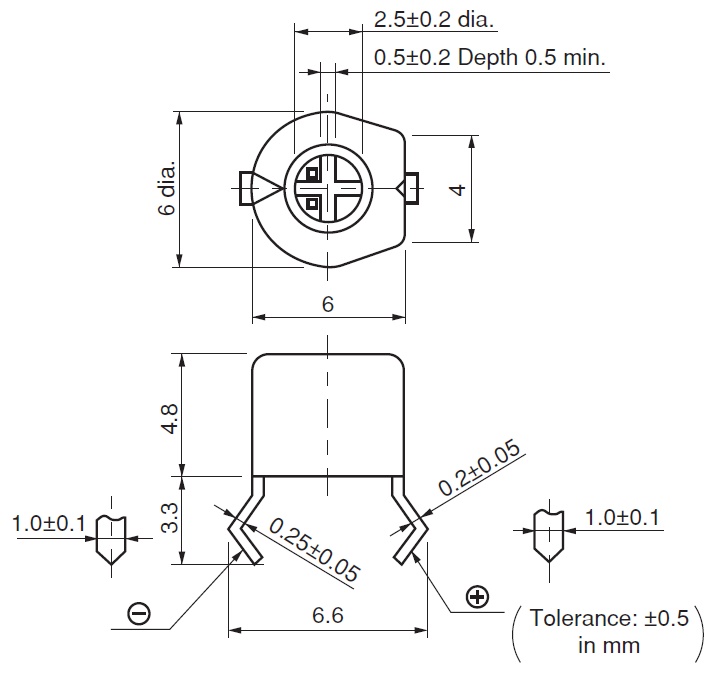
 Here are a few observations on Murata trimmer caps:   1) The yellow cap aka TZ03P450F169B00  is specified as a 6.8 pF to 45 pF trimmer capacitor.   I tried measuring one using a B&K 810C capacitance meter and got a range of 6.8 pF to 55.4 pF. 2) The terminal on the rounded end is directly connected to the brass rotor (verified with an ohmmeter) so it is usually connected to ground in a circuit.   When the round end is grounded a metal adjustment tool will not cause a significant shift in capacitance when it touches the rotor. 3) There are two square "dots" on the brass rotor that give the user an indication of the capacitance setting.  When the two dots are towards the rounded end the cap is at maximum capacitance.  When the dots are at the flat end the cap is at minimum capacitance. 4) Unfortunately Murata doesn't make these caps anymore although there may be subs from other vendors.  Luckily I did buy a bag of 1000 pc. a few years ago so I should be set for life :)

The remaining unsolved battery problem

Image
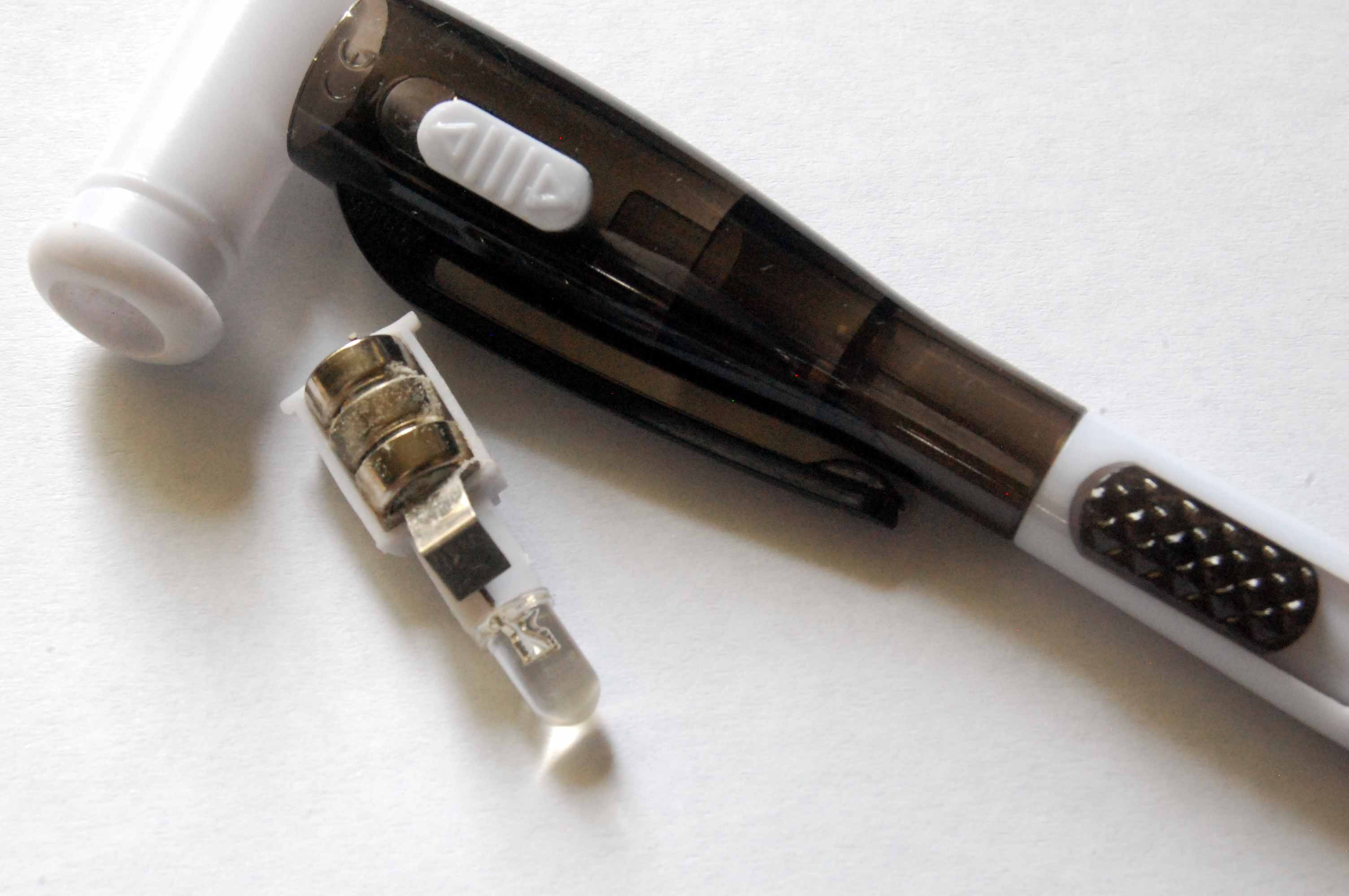
 Leakage problem that is - I have this coffee mug full of pens, I started going through them to see if they still write.  Then I tried turning on an LED light pen, seemed fine.  But a second light pen beam was weak.  Uh-oh ! I opened the second pen up and found this: the dreaded alkaline whiteness ! So I pried out the cells to see how badly the contact is corroded.  It's not too bad but it'll go in the corroded item box to be cleaned and re-used "one of these days". It wasn't that handy a pen anyway, for one thing, the light shines the opposite way from the pen tip, so not much good for writing in the dark. Will anyone ever solve the battery leakage problem for button cells the way the Energizer Ultimate Lithium AA, AAA and 9V batteries did ? https://wb9kzy.blogspot.com/2022/03/the-time-change-on-march-13-2022-brings.html I can only hope. Best Regards, Chuck, WB9KZY http://wb9kzy.com/ham.htm

VE3DNL calibrator as an audio source

Image
 The VE3DNL calibrator was mentioned previously: https://wb9kzy.blogspot.com/2023/07/blinking-led.html http://www.wb9kzy.com/ve3dnl.htm This design was meant by Glenn, VE3DNL, to output receiver calibration markers at 5, 10, 20 or 40 kHz intervals throughout the HF bands.  But the CD4060 chip has other output pins with other division ratios.  Pin 2 of the CD4060 divides by 8192.  With the stock 5.12 MHz crystal this division will output a nice 625 Hz square wave: Here are the frequencies output with the other pins: There are several crystal frequencies which output even Hz in the audio range: Note that the first 3 crystals are 1/2 the frequency of the last three. I had both 4.9152 and 6.144 MHz crystals on hand so I also tried them on the VE3DNL (pin sockets on the crystal position made this easy): 4.9152 MHz divided by 8192 6.144 MHz divided by 8192 Here are the frequencies of both the 4.9152 and 6.144 crystals output with the other pins: The VE3DNL calibrator is a handy and versatile

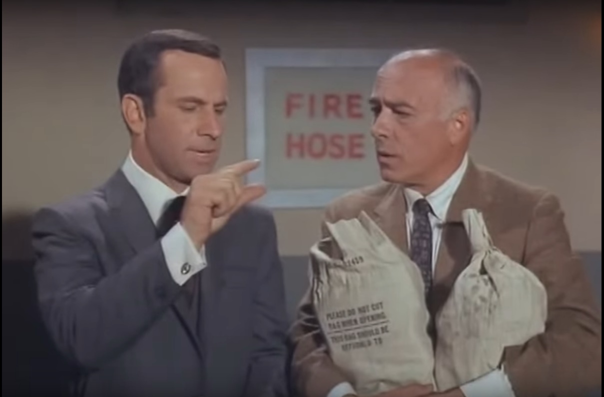
Missed it by that much

Image
A customer emailed about keying an FT-101EE with a stock PK-4 keyer kit (no SSR) that he had purchased.  Looking at the FT-101EE schematic it seemed like there was no typical cathode (positive) OR grid block (negative) high voltage involved.  So I mentioned that the keying voltage and current should be measured first but that it looked like it might work without the SSR. BZZZZZT ! After building the PK-4 the customer emailed and said that while the measured keying voltage (11.3 volts) and keying current (6.5 mA) were relatively low, the PK-4 caused a key down condition when hooked up.  The PK-4 output transistor tested OK with an ohmmeter.   Unfortunately even though the voltage and current were low, the voltage polarity was negative.  Digital volt meter strikes again !  It can be easy to miss that little negative sign on the display.  An analog VOM will pin (sometimes audibly) with a negative voltage or current.  The negative voltage is a problem because there is an inherent diode bet

Blinking LED

Image
. The blinking LED I got from Mouser, 804-WP56BID by Kingbright, works fine.  But the 40 mcd brightness rating means it can be harder to see in high light levels. https://www.mouser.com/ProductDetail/Kingbright/WP56BID?qs=58z0TXQGVSSigALogKJCBg%3D%3D So it occurred to me:  why not add a regular high brightness LED in series with the blinking LED ?   I tried it and it works nicely, the series resistor can be tweaked due to the increased voltage drop across two LEDs versus one but it's not super critical. And then another idea:  use a blinking LED to "gate" an oscillator, specifically a crystal calibrator.  Crystal  calibrators, for example the Model 226 from Ten-Tec: https://www.qsl.net/w/wb4kdi/TenTec/226_Calibrator.pdf used to offer this capability, it made it easier to spot a calibration signal with a receiver.  So I tried this with a VE3DNL calibrator: http://www.wb9kzy.com/ve3dnl.htm It worked OK.  At 10 MHz the calibrator signal is shifted up about 10 Hz and the sig

Ideas

Image
Every once in a while I look at electronic project idea sites.  Here are "some" good ones: http://www.redcircuits.com/ http://www.sm0vpo.altervista.org/ http://ludens.cl/Electron/Electron.html http://techlib.com/default.htm In a way these sites are the internet equivalent of my old favorite "101 Projects" magazines which can be found on the wacky,wonderful, World Radio History site: https://worldradiohistory.com/Hobbyist_Special_Editions.htm my favorite is the 1974 version: https://worldradiohistory.com/BOOKSHELF-ARH/Technology/Hobbyist-Specials/101-Electronics%20Projects-1974.pdf I'm not necessarily going to copy/build a circuit but might get an idea from something presented.   BTW, "some" to me indicates the number of 4, I read that once in a comic book - I don't remember how to diagram a sentence, how to extract a cube root or Maxwell's equations but that one panel from a comic book, yes, although I don't remember anything else from that

Oppenheimer

Image
Veritasium released an interesting video on Oppenheimer: source: https://www.youtube.com/watch?v=Xzv84ZdtlE0 A few items caught my eye: Oppenheimer tried to poison his tutor at Cambridge with a poisoned apple ?: Hahn and Strassmann split the uranium atom on a tabletop ? (it almost looks like a ham rig other than the Erlenmeyer flask) Oppenheimer wasn't the kind of person to worry about mentioning his family :) Oppenheimer had ants in his pants ?   Sperm whale oil ?  I never knew about this !  Good thing that Uranium was so hard to enrich: I'll probably not see the actual movie for some time, but I'm sure it will be fascinating. The video mentions Heisenberg but as was told in this book: https://wb9kzy.blogspot.com/2022/06/book-report-griffin-by-arnold-kramish.html the allies really didn't have to worry about a Nazi atom bomb, Heisenberg never really made an effort. Best Regards, Chuck, WB9KZY http://wb9kzy.com/ham.htm

Class B audio amp with auto bias

Image
 While looking for the Knight kit KG-207 telephone amplifier documentation https://wb9kzy.blogspot.com/2023/07/50-years-ago-was-50th-anniversary-of.html I found the hardcopy of this EDN Design Idea: https://www.edn.com/class-b-amplifier-has-automatic-bias/ I had tried this before but thought I'd reconsider it as far as a possible LM386 killer.  First I thought I'd try entering it into LTspice: But I wasn't able to get it to accept the TI TLV271 spice file, LTspice is still largely a mystery to me :) Then I thought just for expediency, try an LT1793 Linear Technology op amp in place of the TLV271: This does simulate (after I also spec'd a value for C1) but I didn't take it too far since the currents involved were already way past the 2.7 mA idle current of the NJM386.   Also using an opamp isn't right since this is supposed to be an all-discrete circuit.  One final problem is that the circuit (as configured) has no voltage amplification - it's really more of

Unpersons

Image
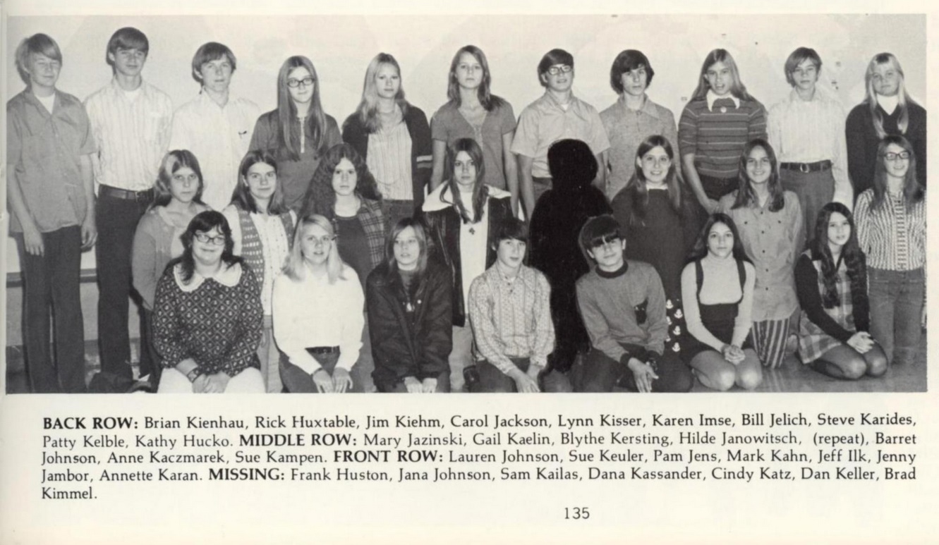
I was looking through my 1973 Nicolet High School yearbook: https://archive.org/details/nicolet73f Page 156 and up were the seniors (I was one in 1973) and they each got an individual picture but the underclassmen on pages 132 to 155 were by alphabetical groups (Nicolet had gotten rid of homerooms). But starting on page 135 student pranksters showed up who wanted to appear multiple times in the yearbook.  But the yearbook staff fought back with their Sharpies and didn't give the pranksters any satisfaction. My total count was 76 of these wacky jokesters. Of course this has been done before, for example in Stalin's USSR: https://wb9kzy.blogspot.com/2023/05/farewell-facebook.html In previous yearbooks when pranking occurred the yearbook staff just labeled the students as repeats but left the picture as is.  There were also young people who extended certain digits, sometimes they would slip through the yearbook staff. . This was 1973 not 1984 but yikes ! I can remember my Dad tell

50 years ago was the 50th anniversary of Radio Shack ?

Image
I was looking for the schematic for this: from an auction site The KG 207 was a Knight kit telephone amplifier that I built.  All I found here was the speaker and the build instructions, I still have to find the actual amplifier and the schematic. However I did sorta find it in this 1973 Allied Radio Shack catalog: The cover says it is their 50th anniversary.   And of course that was 50 years ago so technically 2023 is their 100th anniversary, but their website really doesn't seem to care: https://www.radioshack.com/ It's a shame.  Back to the KG 207, it is a 4 transistor, 2 transformer amp, looks to be similar to the Heathkit AM radio amp that I tried out a while back: https://wb9kzy.blogspot.com/2023/07/try-of-3-transistor-audio-amp-build.html So no need to pursue it further as far as LM386 killer material, the transformers disqualify it.   Here is the KG-207 build manual (folder of 8 jpg pages): https://www.dropbox.com/sh/psdfy1xpxokydwn/AAB1V1hf607emDxdis99fSmaa?dl=0 Best R