Posts

Showing posts from February, 2022

Adding an audio amplfier to the Wien bridge single pot audio oscillator

Image
 Since one quarter of the LM324 quad op amp was unused by the Wien bridge oscillator, I thought that it could be used along with a complementary output transistor stage as an audio amplifier.   I found this page of audio amplifiers by VE7BPO and thought that the  Popcorn Audio Amplifier might work in this situation (near the bottom). https://web.archive.org/web/20140321154315/http://www.qrp.pops.net/af-amp-2008.asp   However (as you might expect) instead of following the design as presented I messed around with it. Audio amp on top, Wien bridge oscillator on bottom   amplifier on breadboard, note nylon bolts/nuts One change to the design is the transistors, the NPN is a 2n4921, the PNP is a 2n4918.  They don't seem to be a complementary pair as I measured an Hfe of 255 for the PNP and 80 for the NPN.  But I had them on hand.  They aren't available anymore from the usual suspects (Mouser / Digikey).  They are both in a TO-225 package. Another change to the VE7BPO design was to u

Wien bridge audio oscillator keying: SOLVED ?

Image
 Taking another look at the Wien bridge single pot audio oscillator circuit and keying.  After trying the 2n7000 across the various gain control feedback resistors (R10, R5, R9) it occurred to me to try the 1n4148 diode pair.  The keying idea is to lower the gain of the circuit below one overall which is required for a sine wave oscillation.  Since the 2n7000 is ON when the gate is several volts above the source this works perfectly for keying.  When the gate is pulled low by the key the 2n7000 is turned off which allows the circuit to oscillate.  The RC pair on the 2n7000 gate results in a nice ramp down of the tone (in my opinion, others may find it mushy ?).  Note that the ramp up is from the oscillator start-up. But the problem with the keying circuit was a leading edge glitch that resulted in a popping noise at the start of the code element (keyed tone).  Then I tried connecting the 2n7000 via a series capacitor thinking that the direct connection may have caused the glitch - no h

Just spray on some Click-b-gone ?

Image
Working with an audio amplifier (see 2-25-2022 blog entry) I had noticed clicking when the volume was all the way up.  It appeared to be from an electric fence that I can hear on the K2 on 80 meters.  But the clicks weren't coincident. The theory I came up with is that possibly the audio amplifier clicking was coupled in via the power lines somehow and detected by the rectifier diodes in the AC power supply.  I tried soldering bypass capacitors across each of the 4 diodes (on the back of the circuit board).  This seems to have gotten rid of the clicks. bypass caps on back of rectifier board top side of board with rectifier diodes But this still doesn't explain why the clicks weren't at the same time from either the 80 meter groundwave (presumably) or the power line. If I hook the 40 meter dipole to the audio amplifier input and crank it up I can hear the electric fence clicks but they are coincident with the ones on the K2. I will just let the matter drop for now, there'

In the process of chasing a glitch

Image
I was looking for this leading edge keying glitch on the Wien bridge audio oscillator: the Wien bridge clicker Haven't found the cause yet but I'll keep looking. During the process of looking I happened to turn up the gain on the audio amplifier all the way.  Even though the oscillator was off and I wasn't doing any keying I was hearing a clicking sound. 2 clicks on the audio amp, 1st about 4 divisions from the left and the 2nd just after the midpoint It wasn't anything on-the-second, there are about 10 clicks in 14 seconds, so close but it can't be a clock as such. Then I turned off everything in the house except for the amplifier.  The lights, computers, router, everything off.  The click was still there It then occurred to me that it might be an electric fence.  I turned on the K2 and tuned to 3550 and there it was.  Usually the noise blanker just wipes it away so I don't notice it. electric fence clicks on about 3550 kHz about 5+ divisions apart, about 1.4 s

Wien bridge audio oscillator keying

Image
 Here is a quick schematic of the original PA0RDT single pot Wien bridge audio oscillator design with a couple of slight changes but no keying: redrawn PA0RDT Wien bridge oscillator Next a first attempt at keying by using a 2n7000 MOSFET to short out the 100k ohm feedback resistor on the output op-amp U1A. Wien bridge oscillator plus keying transistor   When the key is up the gate of the 2n7000 is high and the transistor is ON which shorts out the 100k ohm resistor and stops oscillation.  When the key is pressed the gate goes low and the transistor turns off.  The feedback resistance returns to 100 k ohms and the oscillator starts. However as can be seen in the scope screen capture there is a glitch right at the start, then a decent ramp up to the full sin wave.  But then the key goes up, the output goes off with a glitch and no shaping (thumping). glitch at the start and no shaping at the end Finally a second attempt was made by changing the 2n7000 pullup resistance to 100 k ohms and

single pot Wien bridge audio oscillator

Image
Hewlett-Packard started in the late 1930s with a Wien bridge audio oscillator product, the 200a.  the original HP product This was based on a clever design by Hewlett that used a light bulb's changing resistance to stabilize the gain of the oscillator.  But the frequency was varied with a 4 gang variable capacitor that must have been fairly expensive even in 1939. Wow, just like an SX-88 ! Later versions of the Wien bridge audio oscillator use a dual pot to vary the frequency.  The dual pot is more expensive and harder to find than a single pot.  Also with a dual pot, another dual pot would be used to provide fine tuning. schematic of Wien bridge audio oscillator The dual pot Wien bridge audio oscillator, fine tune dual pot on right (actually there are two Wien oscillators, the one on the right has a fixed frequency)   With a single pot Wien bridge audio oscillator either another single pot could be used for fine tuning or the expensive route: a 10 turn unit could be used to take t

Heathkit MR-1010 digital dial 3

Image
 I tried the DL4YHF2 frequency counter / crystal tester that I bought on Ebay as a digital dial for the Heathkit MR-1010.  Here is a very well done manual for it:   https://z100lifeline.swvagts.com/articles/DL4YHF2Manual.pdf   The counter doesn't have an input amplifier so I used a prototype for the Counter Preamp kit ( web page: http://wb9kzy.com/preamp.htm ) to convert the local oscillator to digital level signals. counter preamp prototype just hanging there counter preamp schematic (discontinued kit) A signal generator was used to set the offset frequency to 453 kHz so the counter now functions as a digital dial. MR-1010 tuned to WDBC Escanaba 680 kHz While it works I think the next step will be to mount the preamp inside the MR-1010 and then route the preamp output to a jack.  Another jack for power will also be added.  This way the actual display can easily be changed as desired.  This DL4YHF2 counter is a little dim as currently constructed, I had to shade the LEDs to be abl

Heathkit MR-1010 display

Image
I was going to try and fix/replace the frequency display in the Heathkit MR-1010 direction finder radio (see https://wb9kzy.blogspot.com/2022/02/the-heathkit-mr-1010.html  ) inside view of the Heathkit MR-1010 so I tried hooking up an LCD counter I purchased on Ebay.  I set the LCD counter to a 0.453 MHz IF with a subtract (high side Local Oscillator (LO) injection).  The external counter was easy to hook into the MR-1010 via the yellow wire coming from the LO to the counter input. The yellow wire connects the Local Oscillator to the display But then I did try the internal counter and it started to work again.  There is still something wrong though, in spite of the Faraday cage in front of the display (you can see the wires in the picture) and the feed through caps and all the other shielding precautions that Heathkit took there is a lot of interference when the internal counter is ON. WDBC in Escanaba MI tuned for maximum meter reading   Also, the radio uses about 30 mA at 9V but wh

Voila a photo-transistor !

Image
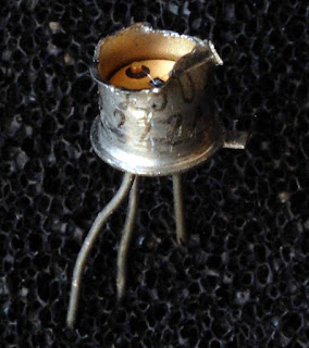
Still looking at the pulse sensor for the exercise computer (see 2-17-22 post) I looked through my inventory of parts and junk for photodiodes and phototransistors.  I did find some photodiodes and in a pinch an LED or a glass bodied diode might also function as a photodiode. But no phototransistors were found (at least none that were labeled as such).   I could buy some photo-transistors but then there is that delay factor where when you finally receive something you've already moved onto some other project, the purchased item gets shelved and some time later upon finding the purchased item  you wonder:  "why did I buy this ?" :) So after some internet searches I realized that a metal can transistor could be converted to a photo-transistor by removing some of the metal.  After finding a bag of 20 2n2222 metal can transistors from Central Semiconductor I then got a coping saw and set to work.  I sawed through the can to where I could fit the tip of my diagonal cutters an

Informed Delivery and LOTW

Image
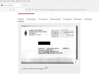
 I finally signed up for LOTW (Logbook of the world)   on February 9, 2022.  In the US the ARRL then sends a postcard with a verification password printed on it.  I've been waiting 10 days now and Eureka ! I found it on USPS Informed Delivery the morning of February 19, 2022: My LOTW postcard with the magic number blacked out It looks like there is a strip of tape over the (incorrect?) barcode at the bottom of the postcard so I assume that that was what caused the long transit time from CT to WI. I tried punching in the number (lucky it was on the front of the card, Informed Delivery doesn't show the back) and it worked: the LOTW confirmation screen cap So now I have to wait for the next step in the process (probably Monday as it's a Saturday today).   Then I need to get back on the air, which isn't going to happen until it's warmer than 10F and the crazy wind dies down so I can get outside and fix those antennas. Best Regards, Chuck, WB9KZY  http://wb9kzy.com/ham.

Including IC Sockets with Kits

Image
 One thing I've always done with the kits is to provide sockets for as many of the ICs as possible.  This is for the DIP (Dual Inline Package) ICs.  Surface mount IC sockets are either unobtainium or too expensive.  TO-92 sockets for regulator ICs can also be hard to find / expensive.  Sometimes with a low cost kit I'll make the socket optional.  Why include sockets with a kit ? It's not for reliability, sockets might actually be less reliable than soldering an IC in place.   It's because of this kit: Modified Ramsey 40 meter DC receiver with sockets and the NE602 on vacation I bought a kit version of the Neophyte receiver (from February 1988 QST, page 14) during the late 1980s/early 1990s because the NE602 mixer chip at the heart of the Neophyte was close to being unobtainium at the time.  The hobby accessible distributors like Digi-key and Mouser didn't handle Signetics parts (the vendor of the NE602 prior to purchase by Philips).  Radio Shack didn't have them

Sometimes the old tricks fail . . .

Image
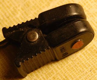
. . . OR is that IR LED working ? I remember being at work talking with a tech repairing an IC handler (used in automatically testing DIP packaged ICs) - this was in the 1980s. He was checking some optical sensors used to keep track of the IC chip progress through the handler.  The sensors used an IR LED and a phototransistor pair to sense the IC passing by. He pulled out what looked like a small Popsicle stick with faint yellow paint on the end.  It was some kind of chemical that glowed when the IR light shined on it. Fast forward to 2022, I am looking at a pulse sensor from an exercise computer which I *think* uses the same concept: an IR LED plus phototransistor.  This pair is mounted on a clip that is put on your ear lobe while exercising.  The amount of IR light from the LED reaching the phototransistor is modulated by a person's pulse.  I'm not quite sure which of the two items is the LED and which is the transistor. the pulse sensor a stock photo of the pulse sensor and

The French Atlantic Affair

Image
 I started watching a movie on the internet, "Executive Suite" Which can be found here:  https://archive.org/details/ExecutiveSuite1954  but before the credits were over I noticed the screenwriters name, Ernest Lehman.   For some reason I remembered that name.  Then it came to me, Mr. Lehman (a ham) had also written a novel and TV screenplay: "The French Atlantic Affair" which involved ham radio.  I had read something in QST about this, so the ARRL Periodicals Search and Archive found this from August 1977 QST, pages 56 & 57, ARRL members can view it here: https://p1k.arrl.org/pubs_archive/70339 Mr. Lehman was a pretty famous author / screenwriter (notably the original screenplay for the Hitchcock movie "North by Northwest") but I remembered him due to ham radio ;) From there it was fairly easy to find the book on the internet archive: https://archive.org/details/frenchatlanticaf00lehm/page/n6/mode/2up This is an adventure book in which ham radio play

101 Electronic Projects magazine

Image
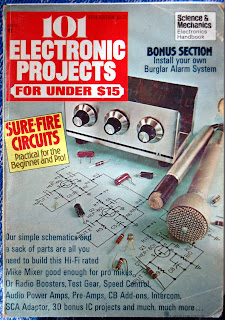
 This 1974 edition of 101 Electronic Projects (for under $15) is one of my favorites.   Not sure why, none of the projects are shown built or photographed, just schematics and a few comments.  They made a few additions/deletions with every annual issue.  But it was a fun source of inexpensive (cheap) project ideas.  Of course the superb web site World Radio History has this issue: https://worldradiohistory.com/Archive-Hobbyist-Specials/101-Electronics%20Projects-1974.pdf along with a nearly complete collection of these compilation magazines like the Electronic Experimenters Guide and others (almost every electronics magazine published one): https://worldradiohistory.com/Hobbyist_Special_Editions.htm Archive.org also has this 1974 issue: https://archive.org/details/101ElectronicsProjects1974/mode/2up While looking through this 1974 issue this scrambler project on page 29 caught my eye: It uses a diode bridge configuration (same as in a power supply) which is different from what is norma

A "prequel" to Similarities in Wave Behavior

Image
The short educational film from 1959: "Similarities in Wave Behavior" is must-see TV for any ham radio operator.  Dr. John Shive gives an intuitive presentation of how waves propagate along transmission lines.  It's nice to see something demonstrated rather than just hearing a lecture. But another film that Dr. Shive made on the subject was "Simple Waves" - if you haven't seen "Similarities" before, "Simple Waves" would probably be the one to watch first - it functions as an introductory film.  "Simple Waves" was part of the PSSC physics curriculum used by high schools in the 1960s and 1970s:   BTW, I actually bought a copy of the "Similarities in Wave Behavior" video on VHS tape in the late 20th century.  But ATT was wonderful enough to post a copy on Youtube: I really think it's worth the time to watch and re-watch both films.   "Similarities in Wave Behavior" was also mentioned in the December 1961 i