Understanding the MOSFET rectifier circuit
After doing a little more simulating with LTspice I can see why my simple effort at a MOSFET rectfier for the economy bipolar supply didn't work. The reason is that as long as the MOSFET is ON, the channel conducts, in either direction ! So it's not like a diode where the conduction ends roughly when the cathode and anode are at equal voltage. Thus with the MOSFET the output voltage follows the waveform back down because the MOSFET discharges the capacitor into the AC input voltage source (transformer). This also explains why the MOSFET gets warm, the rather large cap is being charged and discharged each cycle through the MOSFET.
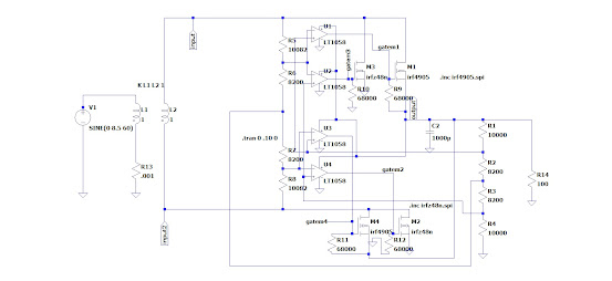
The opamp (as a quad comparator) and the pair of voltage dividers are used to turn on the MOSFET only when the input voltage is higher than the capacitor voltage.
I added some probe points on the 4 gates of the MOSFETs in this schematic and also added a more substantial 100 ohm load:
 |
| MOSFET rectifier with gate probes and 100 ohm load |
And looking at the two p-channel MOSFET gates, gatem1 and gatem4, it can be seen on the simulation output how the gate voltage turns on for the first quarter cycle for gatem1 (MOSFET M1) and then shuts off the gate drive just after the peak AC voltage. Something similar can be seen in the second half cycle where the gate of MOSFET M4 turns on only when the AC voltage exceeds the positive voltage on the output cap.
 |
| rectifier output with gate waveforms |
If the 100 ohm resistor is removed the light loading of just the comparator voltage divider string results in just a blip where the MOSFETs are turned on.
 |
| output and gate waveforms with minimal load |
This is very clever and I can see why the circuit was made so complicated, no opportunities for "Muntzing" that I can see :)
https://www.electronicdesign.com/technologies/boards/article/21771148/whats-all-this-muntzing-stuff-anyhow
Best Regards,
Chuck, WB9KZY
http://wb9kzy.com/ham.htm