Multiple Feedback Bandpass Filter Analysis and Design
Somewhere I had a spreadsheet to de-compile and design active bandpass filters. I can't find it right now so took a look on the internet for online filter calculators, the first two in the search results were:
for de-compiling an existing filter design: http://sim.okawa-denshi.jp/en/OPttool.php
for designing a new filter: https://www.ee-diary.com/2021/11/how-to-design-multiple-feedback-band.html
So I took a look at the 4 stages of bandpass filters mentioned in the low-IF blog post:
https://wb9kzy.blogspot.com/2025/01/low-if.html
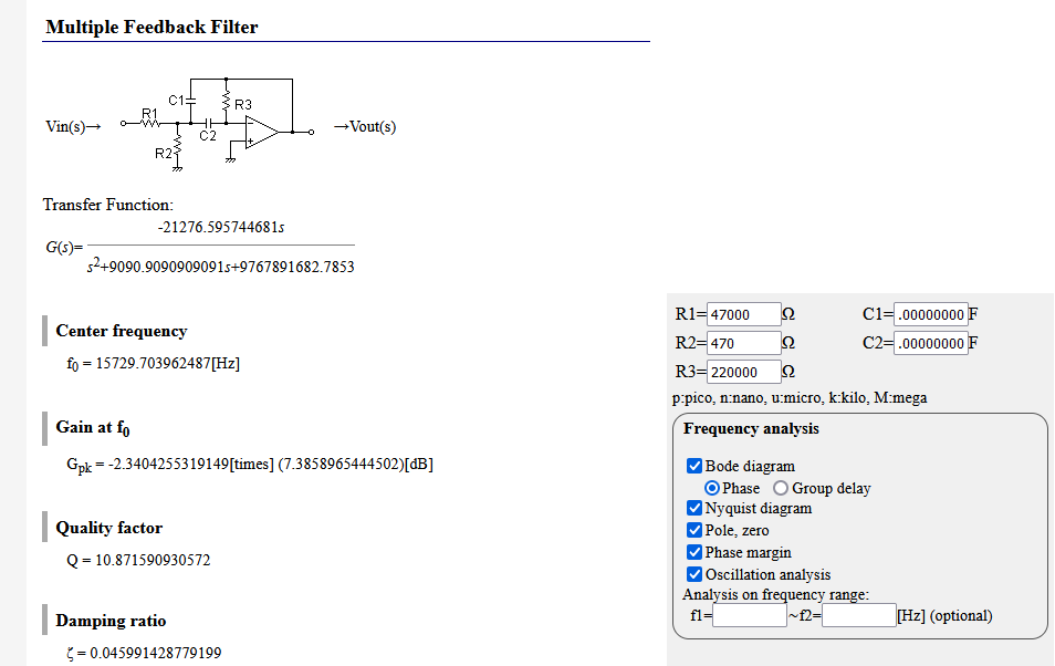
W6IOJ mentions in the article that there are four identical stages which are tuned in pairs to two different frequencies. But the gains will also vary as there are 3 different values for R1 (the resistor at the input) 47k ohms (twice), 33k ohms and 22k ohms. Using the first site here are the results:
W6IOJ says that there is unity gain between the audio input and output so those three different R1 values change the gain so that the sum cancels out the loss through the mixer. In this case adding up the gains: 7.4 + 7.4 + 14 + 10.5 = 39.3 dB of loss through the mixer, that is interesting. Looking at it via voltage gain that is 3.33 x 5 x 2.34 x 2.34 = 91.2 times the input signal (40 db would be 100x the input). Of course this assumes equal impedances, blah blah blah :) Note that the Q's are roughly 11, this is about twice what was recommended in Solid State Design by DeMaw and Hayward for audio active filters.
Now after reviewing the design it's probably time to gather parts and build !
Best Regards,
Chuck, WB9KZY
http://wb9kzy.com/ham.htm


