Measuring output impedance
It occurred to me that part of the problem with the VE3DNL Marker Generator and the strength of 10 kHz harmonics at the upper HF range might be due to fixturing:
https://wb9kzy.blogspot.com/2023/08/unsolved-mysteries.html
I was using a gimmick cap to connect the TinySA to the VE3DNL, and as a capacitor the response would vary with frequency. And the VE3DNL output has to be attenuated somehow to avoid damaging the TinySA. No better way to do this than with a resistive attenuator which shouldn't vary in response the way a simple gimmick cap would.
So the first step is to determine what the output impedance of the VE3DNL Marker Generator is. This site suggested a method:
https://electronics.stackexchange.com/questions/6917/measuring-output-impedance
Another way of doing this would be to use a pot and vary it until the output decreased by 1/2. I wasn't so sure any of the pots I have are good enough RF wise for this, so I just used some fixed resistors (50, 150, 252 and 300 ohms):
 |
| 50 ohms |
 |
| 150 ohms |
 |
| 252 ohms |
 |
| 300 ohms |
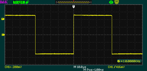
It looks to me like the unloaded output voltage is about 9 volts, so 1/2 of that happens somewhere between 252 and 300 ohms.
 |
| no load |
So the next step is to figure out how much attenuation we want and then what attenuator design to use to obtain that, transforming 275 ohms or so of the VE3DNL Marker Generator to 50 ohms of the TinySA. Also, looking at these scope photos, need to recheck the probe compensation !
Something to do in the future ! :)
Best Regards,
Chuck, WB9KZY
http://wb9kzy.com/ham.htm