Economy bipolar supply
When I was in college we learned about op-amps, and the circuits were always powered with a bipolar supply where the positive and negative voltages had the same magnitude differing only in sign. The op-amp circuits had no coupling capacitors between stages. There were no elaborate schemes on the + pin of the op-amp to simulate a ground. Life was easy.
But in the real world, both ham radio and otherwise, bipolar supplies are rarely used. Our fellow travelers, the audiophiles, would use them to get rid of the large coupling cap on the output of an audio power amplifier. But most consumer electronics used single polarity supplies including ham radio where the +13.8 Volt supply became a standard.
However with some circuits like the micro-ammeter circuit
(see https://wb9kzy.blogspot.com/2022/04/microammeter-add-on-circuit-for-dvm.html)
using a single polarity supply just isn't that easy. So two 9V batteries are used - this works well but it can be a hassle, I'm usually yanking them out of some other project to stick them into another.
So here is a possible economy solution: using an old AC output wall wart:
 |
| yes, that is an RCA plug on a power supply |
The AC waveform on the output of the wall wart is really ugly:
 |
| and I don't think it's the fault of the transfotmer |
It peaks at about plus or minus 15 volts.
A two diode half-wave rectifier into a 78L09 regulator for the positive voltage and an op-amp plus a PNP output transistor for the tracking negative output.
 |
| Economy bipolar supply schematic |
A 79L09 (or whatever the negative 9 volt regulator part number actually is) could probably be used instead of the op-amp and transistor but I didn't have any on hand.
The circuit provides up to 30 mA without breaking regulation. Here with a 300 ohm load are the negative and positive readings. This should be more than enough for the micro-ammeter circuit.
 | ||
| positive almost 9V reading |
 | |
| negative supply reading |
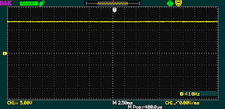
The no load filtered voltage is about 13.5V as seen in this scope capture:
 |
| no load no problem, positive unregulated voltage |
here are scope captures of the 30 mA load voltage & magnification of the ripple
 |
| 30 mA load voltage |
 |
| 30 mA load, magnified ripple |
Now if we had access to a center tap output a full wave rectifier could be used for less ripple and probably more output for a lot of applications like the micro-ammeter this should work fine, we'll see.
Best Regards,
Chuck, WB9KZY
http://wb9kzy.com/ham.htm