Keyer Test Fixture
Here is a test fixture for 8 pin keyer chips that I still use daily even though it's old enough to vote:

Started with a cut down Vector 3677-6 protoboard which has similar traces to a solderless prototype board.

Then built a keyer circuit on the board (the PK-2): http://wb9kzy.com/pk2a.pdf
However instead of a regular socket, used a ZIF (Zero Insertion Force) socket. Also, made many of the connections: the timing capacitor C6, the output transistor Q1 and the voltage regulator U2 with pin sockets. That way it's easy to test out other chips/transistors/capacitors without requiring a soldering iron. A piece of cut down 2x4 softwood was used for the sides. A saw kerf was cut into the wood to hold the circuit board. Two aluminum plates were attached to the wood to hold everything together. (Drywall screws screwed into end grain !):

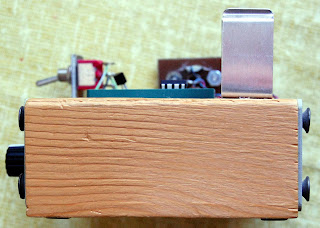


The magic marker isn't as permanent as advertised but after 20 years I do remember what does what :)
BTW, those aluminum end plates were from an HP-1000 computer that we had at work. When some high-speed interfaces were installed on the back of the computer they replaced these aluminum plates with connectors. A friendly request was made and I got them :) They were perfect for this application, the four corner holes had been pre-drilled. The plates were easy to drill for the switch, pot on the front and the paddle, output and power jacks on the back (yes, the power jack is the completely inappropriate RCA).
Since the ZIF socket was so large (they don't come smaller than 14 pins, this one was 24 pins purchased on ebay, Canadian military surplus !) a chip programming site was added with the "bottom" 8 pins in addition to the keyer test on the "top" 8 pins. The middle 8 pins were removed and kept as spares (the top of the ZIF socket can be removed by taking out the two screws).


Note that while this ZIF socket is a genuine 3M Textool, the ones on ebay: TFXTDOL, especially the 14 pinners work fine.

Various things have been added and removed over the years including a 3 position power switch that has proved very handy since it can not only turn off the power in the middle position but also quickly "quench" the voltage regulator cap in the down position. This ability to quench is handy with low power regulators which will continue to supply power to the keyer chip for an extended period even though the battery is disconnected.
After using this fixture for 20 years about the only repair required was the replacement of a noisy speed pot in 2021. I switched to a smaller knob so the markings for the speed pot resistance aren't quite as easy to read.
With appropriate socket adapters it's possible to use this test fixture with surface mount keyer chips, too.
A tip: one thing we did at work was to periodically turn a test fixture over and rap it on a table top. This would dislodge any little chunks that had made their way into the ZIF socket. Apparently finely ground walnut shells were used during the IC fabrication process to clean either the molds or the ICs or both. Some of this grit would cling to the ICs and then dislodge into the sockets. Of course this only happens when large volumes of ICs are handled, not likely in my business :)
Best Regards,
Chuck, WB9KZY
http://wb9kzy.com/ham.htm
Comments